Designing a Modular Battery Pack? Don't Forget These Tips
Developing a modular battery pack is tricky but not impossible if you follow these tips.
June 21, 2021

Anvin Joe Manadan
Battery packs with higher power density and features have multiple modules that work together to form the complete functionality of the battery system. The modules include fuel gauge, protection devices, user interfaces, hot swaps, etc. Most of these modules remain common across projects which opens the possibility to reuse them in other applications. A modular approach that splits the design into multiple modules reduces development time and makes testing easier. Designers also can house modules in individual Printed Circuit Boards (PCBs) that can be selectively swapped with a different module for a new project. It separates battery pack functionalities into individual boards that can be tested and verified before combining them to form the complete pack. This reduces the development time as the work can be split among various team members. The article describes the modular approach in designing battery packs along with the advantages and challenges involved. An example is considered to highlight the process.
The major modules in a battery pack are included below.
Cells: The individual cells are arranged in a series and/or parallel combination to attain the power levels required for the application.
Heater: This is optional and is used to heat the cells to have the pack operational in cold conditions.
Thermistor: These are temperature sensors placed at multiple positions in the battery pack to measure the temperature of the cells. They are used to protect the pack from over and under temperature.
Analog Front End (AFE): This Integrated Circuit (IC) digitizes the cell parameters such as voltage, current, and temperature. The fuel gauge requires the values for these to compute pack performance parameters such as State of Charge (SOC) and remaining capacity. It is also used to identify abnormal use conditions and protect the battery pack.
Fuel Gauge: This IC uses the values computed by AFE to calculate pack performance parameters such as SOC and remaining capacity. It also activates and de-activates protection devices such as transistors and fuses.
Protection Devices: These include the switches and fuses used to protect the battery pack from conditions such as cell overvoltage, cell under voltage, cell over temperature, cell under temperature, over current, and short circuit current.
Microcontroller: This is optional and is mainly used to provide user interfaces such as buttons and displays.
The above modules, along with interfacing electrical components, are packed together to form a functional battery pack. The designer can house all these components within a single circuit board OR divide the components into groups that can be housed within individual modular circuit boards. These modular circuit boards are then connected to form the complete pack.
Modular circuit board
A modular circuit board consists of one or more electrical components connected to realize one or more functionalities. For example, the inputs required for the functionality might come from another module, for which an interface is provided in the form of a connector or a connection point. The same applies to the output from this module. Once assembled to form the pack, these circuit boards are no more individual but work together to develop the complete battery pack. Some of the functionalities that can be made modular in a battery pack are included below:
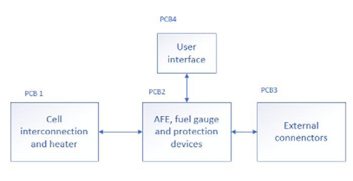
Cell interconnection and heater: High power battery packs consist of multiple cells connected in a series-parallel combination. The interconnection, along with heaters, can be housed in a circuit board. The individual cell voltages and power lines and the heater activation signal can be provided through a connector that can mate to the interfacing board.
AFE, fuel gauge, and protections: The AFE and fuel gauge connects to the cell interconnect board and monitor and protect the pack. The protection devices such as switches and fuses are housed in this board.
External interface: This includes the connectors needed to charge and discharge the battery pack and interfaces with the AFE and fuel gauge board. The external connectors depend on the application and can be easily swapped with a different interface board for another customer whose power needs are similar.
User interface: The user interface can be different for each application and added to the battery pack accordingly. Suppose additional components such as a microcontroller are required to drive the user interface. In that case, it can be added as another modular board, or one of the modules can be changed to add the component.

Advantages with modular design
Below are some of the advantages of the modular design of battery packs.
Reduced development time: Each module can be individually designed and tested in parallel by separate designers. This reduces the time required to complete the design. In addition, each module can be individually tested once they are ready and does not need to wait for other modules.
Re-useability of modules: Once individual modules are developed, they can be used across multiple projects. For example, an AFE and fuel gauge module designed for a 4S9P cell arrangement can be re-used on another battery pack with a cell arrangement of 4S5P or 4S3P.
Selective replacement of faulty module: Damaged battery packs can be brought back to be functional by identifying the failed module and replacing it with a new one. For example, on a battery pack with the protection fuse blown due to a faulty cell, the pack can be repaired by replacing the cell interconnection board and the AFE board with a new one, with the external interface board and the user interface board remaining the same.
Reduced cost per battery pack: In some battery packs, certain regions may need to be flexible depending on the customer's needs. The cost and time required to make a flexible circuit board are higher when compared to a rigid circuit board. With a modular approach, the region that needs to be flexible can be made as a flex board, and the rest can stay as a rigid board. This reduces the overall cost of the battery pack.
Challenges with modular design
There are some challenges involved in designing a battery pack with a modular approach.
Additional connectors and space needed: Each module needs to house connectors to interface with other modules. This increases the Bill Of Material (BOM) cost and consumes space on the circuit board, due to which the size of PCB needs to be higher.
Well-defined architecture required: A well-defined architecture along with modules and inter-connections need to be specified before the actual design phase. The connectors and pins on each module need to be defined and carefully executed across modules. Any variation in pins between connecting modules can result in the modules being non-compatible and needing re-design.
Careful assembly process: The assembly process needs to be defined and executed with care to avoid the modules being connected in the wrong way. Common mistakes are pin offset while connecting modules, connecting in a flipped manner, not connecting all pins at once, etc. Some of these errors can be avoided by selecting polarized connectors to prevent the operator from connecting in the wrong manner.
Loose connections: Loose connections between modules can occur when the pack is subjected to vibrations and stress under normal use cases. This results in an entirely faulty pack or a pack with intermittent faults. This scenario can be prevented by using connectors that lock with each other.
Anvin Joe Manadan is a Senior Electrical Engineer at Inventus Power.
You May Also Like


